TECH
How does Lucas metering work???
What is inside
Electric and Belt drive fuel pumps for the Lucas system
Rebuilding road race metering
SHUTTLE
METERING
Two cylinder example:
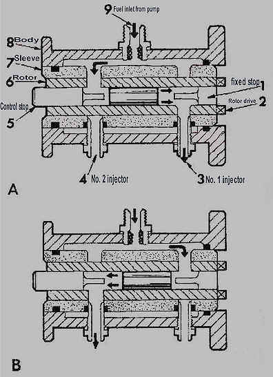
(Fig. 8A) When the engine is started and the rotor turns within the sleeve, the rotor port at the control stop end becomes coincident with the port in the sleeve leading to the fuel reservoir in the body casting. Fuel at high pressure enters the rotor bore and drives the shuttle to the right (i.e., towards the fixed stop end of the rotor). This movement of the shuttle displaces fuel in the rotor bore through the ports in the rotor and sleeve to the injector serving No. 1 cylinder. A further 180 degree rotation of the rotor
(Fig. 8B) causes the rotor ports at the fixed stop end to align with the sleeve
port leading to the fuel reservoir. Fuel now enters at the fixed stop end of the
rotor and drives the shuttle back towards the control stop end. An identical
quantity of fuel is displaced, by the shuttle as it moves to the left, by way of
the outlets in the rotor and sleeve to No. 2 injector.
|
|