|
|
Lucas Service Training Centre
Petrol Injection Mk II
DESCRIPTION AND FUNCTION OF MIXTURE CONTROL UNIT
Figure 10 shows a mixture control unit, which controls the amount of fuel in accordance with the engine requirements, by altering the position of the control stop, and hence varying the length of shuttle travel. The control stop in the metering device is kept in contact with the cam follower by means of the fuel pressure in the rotor. The balance spring, around the cam follower, counteracts the effect of this pressure, and prevents the control mechanism from being overloaded.
The control mechanism consists of a diaphragm, two links, two control springs, a fuel cam and a cam follower. The two control links are attached to the center of the diaphragm by means of a special bearing. Any axial deflections of the diaphragm cause the links to move axially. The roller (attached to the links) moves in sympathy with them, and at the same time maintains contact with the tapered lever (or datum track) and the control stop plunger (or cam follower).
The diaphragm is mounted in a depression chamber at the end of the mixture control unit. The depression chamber is connected to the inlet manifold downstream of the throttle butterflies. Any variation in manifold depression causes the diaphragm to deflect against the action of two control springs.
When there is full load on the engine, and the throttle is open, the diaphragm is held in the rest position by spring pressure. As the engine load is reduced, and the throttle is closed, the increased vacuum causes the diaphragm to deflect. The control links and rollers are then moved into a new position. The control stop is also moved, causing reduced shuttle-travel, and there is, consequently, less fuel in each charge.
The mixture control unit incorporates an excess fuel device, which ensures that extra fuel is supplied during starting. A wire control on the fascia panel is connected to the overfuel lever on the side of the mixture control unit. (This wire control is similar to the choke control cable used with conventional engines).
When starting the engine, the driver obtains the extra fuel by pulling out this wire control. This alters the position of the overfuel lever, and the carrier for the fuel cam is drawn away from the cam follower. The shuttle then has a longer travel. As soon as the driver pushes back the wire control, the carrier is returned to the normal operating position by the action of the tension spring.
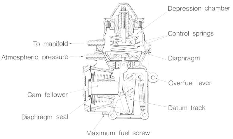
Fig. 10
Page 11
Click here to go to page 12