Lucas Service Training Centre
Petrol Injection Mk II
|
|
|
|
|
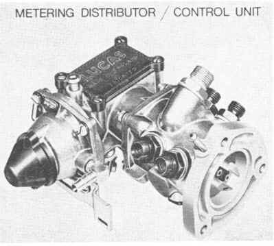
The amount of fuel in each injection, and the frequency of the injections, is controlled by the metering distributor and mixture control unit (Figure 7). The mixture control unit regulates the amount of fuel in each injection, in accordance with the requirements of the engine. The function of the metering distributor is to inject fuel into each individual inlet by a system of shuttle-metering. The two component parts - the metering distributor and the mixture control unit - are a “matched” pair. A faulty metering distributor or mixture control unit should be renewed, and the complete assembly recalibrated. |
|
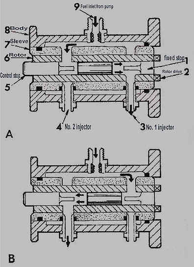
Before considering the design features of the metering distributor, it will probably be advantageous to discuss the principles of shuttle-metering. Figure 8 shows a metering distributor for a twin cylinder engine. It consists essentially of two parts; the rotor and the sleeve. The rotor has two radial ports, which lead to a centre bore containing a shuttle - which is movable between two stops (one fixed and the other adjustable). The sleeve has fuel inlet and outlet ports. The rotor fits inside the sleeve and is connected to, and driven by, the engine. As the rotor turns, the port at the control stop end of the rotor becomes coincident with the fuel inlet port in the sleeve (see Figure 8, top diagram). Pressurised fuel then enters the bore and drives the shuttle towards the fixed stop. This causes fuel to be discharged through the ports in the rotor and sleeve at the fixed stop end, and hence into the first cylinder through the appropriate injector. The lower diagram shows the result of turning the rotor through 180 degrees. Fuel now enters the bore through the port at the fixed stop end of the rotor, driving the shuttle towards the control stop. An identical amount of fuel is then delivered to the second cylinder. As the rotor turns, the pressurised fuel drives the shuttle between the two stops, ensuring that an accurately metered quantity of fuel is injected into the appropriate cylinder at the right time. The low mass of the shuttle ensures a rapid response at high engine speeds. The quantity of fuel injected is the product of the surface area of the shuttle end face and its length of travel. The length of travel is determined by the position of the control stop. The metering distributor shown is for two-cylinder engines. However, the same principles of shuttle-metering can be adapted for four, six and eight cylinder engines, by altering the position and the number of ports in the rotor and sleeve assemblies.
|
Page 9
Click here to go to page 10