|
|
Lucas Service Training Centre
Petrol Injection Mk II
PRINCIPLES OF SHUTTLE-METERING
DESCRIPTION AND FUNCTION OF METERING DISTRIBUTOR
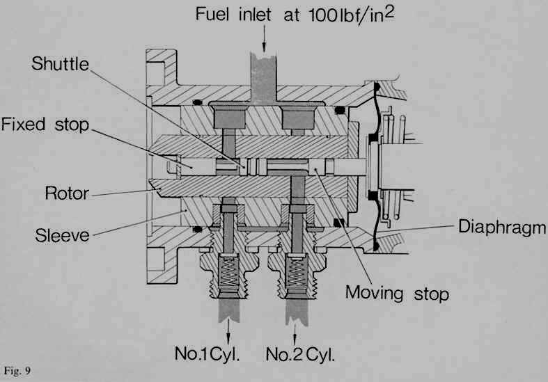
A metering distributor is shown in Figure 9. The rotor and sleeve assembly is made of steel and is supported inside the aluminum body by two ‘0’ type seals. The body has an inlet and six outlets. Fuel in the supply line is maintained at a pressure of 100-110 lbf/in2 (689.50-758.50 kN/m2) by the action of the pump and the relief valve. Pressurized fuel enters the body through the nylon gauge strainer in the inlet. The space between the sleeve, the aluminum body and the two ‘0’ rings is filled with fuel at pressure 100-110 lbf/in2 (689.50-758.50 kN/m2). As the rotor turns, one of the inlet ports in the sleeve coincides with an inlet port in the rotor. Pressurized fuel then enters the center bore in the rotor.
When the rotor turns through a further 60 degrees, another inlet port in the sleeve coincides with an inlet port in the rotor. Pressurized fuel again enters the center bore of the rotor, driving the shuttle towards the other stop. An identical amount of fuel is then delivered to the second cylinder by means of the appropriate outlet and its associated injector.
Every time the rotor completes a revolution, accurately metered quantities of fuel are delivered to each cylinder in turn, by means of the appropriate outlet. There are six outlets (on the Triumph ‘P.I.’ systems), one for each cylinder. All the outlets incorporate rubber ‘0’ type seals, to seal the pressurized fuel in the space between the sleeve and the rotor.
The six outlet unions locate the sleeve in the aluminum body. Leakage fuel is collected in a chamber at the drive end, and is conveyed back to the fuel tank. A small quantity of the leakage fuel is used to lubricate the rubbing surface of the cam follower. It also lubricates the Oldham type coupling, which drives the rotor at half engine-speed.
Page 10
Click here to go to page 11