Maserati Manual MK1
Mistral + 3500 GT Owner's Manual
Control is achieved by adjustment of the position of the control stops which
determine the length of shuttle stroke
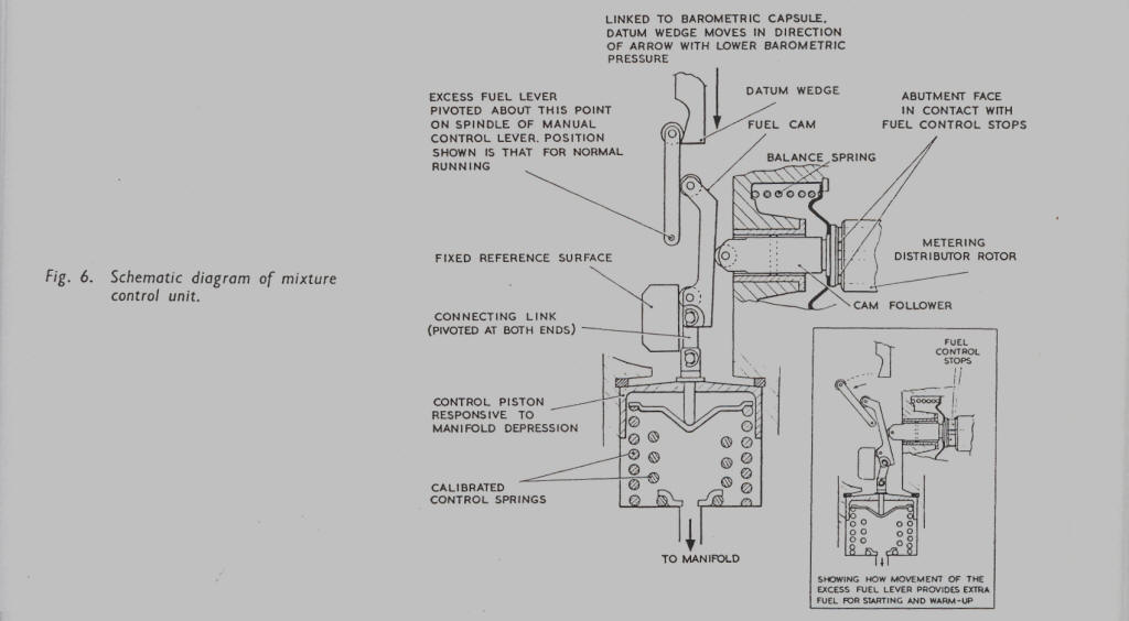
and hence the quantity of fuel delivered. Fig. 6 shows a simplified
schematic arrangement of the control mechanism.
A cam follower has an abutment face against which the control stops in the
metering distributor are forced by fuel
pressure, while at the other end of the follower a small roller bears against a
fuel cam of predetermined slope. The
hydraulic loading of fuel pressure is offset by a balance spring surrounding the
follower, resulting in only light pressure
between the roller and fuel cam. Thus, movement of the fuel cam is reflected in
movement of the control stops. The
fuel cam has a roller at each end, and is connected through a pivoted link to
the main control piston which is backed by
calibrated springs. One of these two rollers runs on a reference surface in the
body of the control unit, and the other
on the track of the excess fuel lever, of which more is said later. The space at
the back of the piston is connected to the
engine down-stream of the throttle so that, as manifold pressure changes, the
position of the control piston alters; this
varies the fuel cam position, so causing the cam follower and control stops to
take up a new setting to maintain the
required fuel-air ratio.
Since operation is by the difference in pressure across the throttle, the same
full throttle stroke will be provided
irrespective of the barometric pressure. Thus as the air becomes less dense, the
mixture ratio applied to the engine
would become progressively richer unless the fuel delivery were reduced
proportionately. In the control unit, this is
achieved by the use of a capsule responsive to changes in barometric pressure.
The capsule carries a wedge which controls
the final setting of the excess fuel lever in its warmed-up position, and so
determines the inclination of the fuel
cam track.
For cold starting, additional fuel and air are required to overcome the friction
of a cold engine and permit it to run
at a fast idle; as the engine warms up, both require to be reduced in step. It
must also be possible to drive the engine
under any load during this period. A manual control is therefore provided which
controls simultaneously the position
(continued)
Page 9
Click here to go to page 10