Maserati Manual MK1
Mistral + 3500 GT Owner's Manual
Construction of Six-Cylinder Metering Distributor
Fig. 5 shows the constructional features of a six-cylinder metering distributor
and mixture control unit. The former
consists of two three-cylinder units combined in one rotor which is driven at
one-quarter engine speed, the inlet and
outlet ports being arranged so that each cylinder receives one injection of fuel
per intake stroke. The shuttles in the
two bores are phased to begin injection at intervals of 120 engine degrees. The
control stops, by means of which the
fuel quantity is adjustable, abut against a face in the mixture control unit,
described below.
A constant pressure pump, operated by a small eccentric cam on the drive shaft,
pumps engine oil at about 105 p.s.i.
which is used for preventing leakage of fuel from the rotor ends and for
lubricating the control stop faces. From the
pump, oil is filtered and fed to a longitudinal drilling in the sleeve, from
which cross drillings lead to two oil grooves,
one at each end of the rotor. At the control stop end, drillings in the rotor
groove lead to the stops, feeding oil through
centres of the stops to the rubbing faces.
The hardened steel sleeve, complete with rotor and shuttle assembly, is floated
in rubber sealing rings in the
aluminum body casting, while between the driving shaft and the rotor driving
plate there is a self-aligning coupling
which allows for any slight misalignment of the rotor and sleeve assembly on its
rubber mounting.
The Mixture Control Unit
This unit is secured to the end flange of the metering distributor (Fig. 5) and
its purpose is to provide complete
control of the quantity of fuel according to load under normal running
conditions, with appropriate corrections for
changes in barometric pressure. In addition, it incorporates a manual control
for cold starting and warm-up conditions.
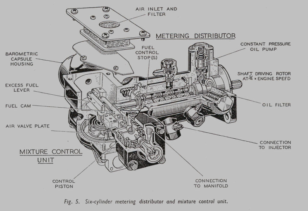
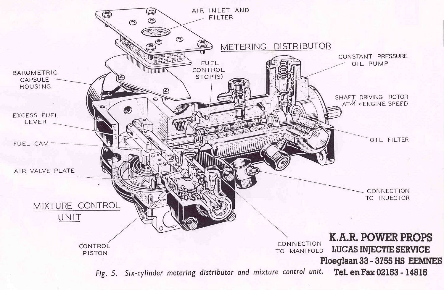
Fig. 5. "super
size" click here
Page 8
Click here to go to page 9