Maserati Manual MK1
Mistral + 3500 GT Owner's Manual
Lucas Injection Dist. - Setting -
1000 deliveries with depression equal.
0 - 1000 deliveries with depression 360mm hg.
1000 deliveries with depression 100mm hg.
Gasoline pumps - Lucas brand - working pressure 7 atmospheres(102-110
p.s.i) minimum capacity - 1500cc a minute.
Minimum number of revolutions at 13 volts -2700 RPM. Maximum power absorbed
under load- 6.5 amperes.
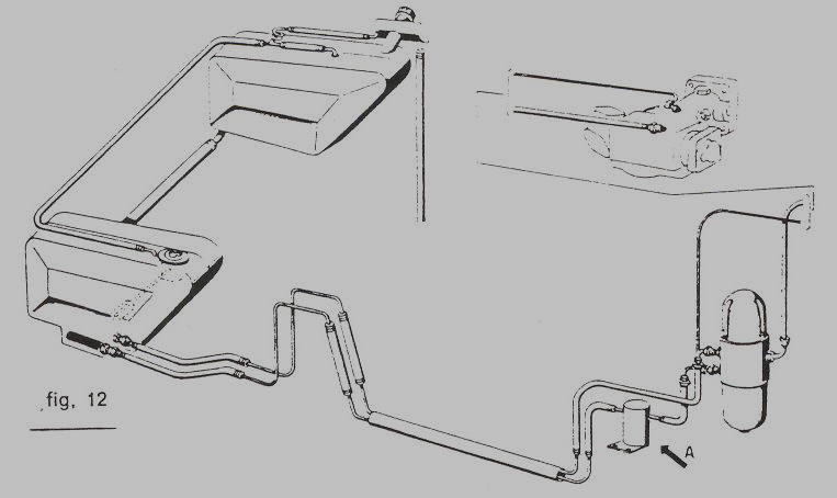
GASOLINE TANK FILLER -You can fill up the two gasoline tanks located on
both sides of the trunk through
one gasoline tank filler, which is located under a locked small door. The
key is the same used to lock the rear window and
the main door. The two tanks are located at different heights and are connected
by a large transfer hose. However, during
the final phase of the filling up of the tanks, you should slow down slightly
the pouring of gasoline to prevent any air or
gasoline reflex and to facilitate the complete fill up of the tanks. The filler
has a cap without the vent, perfectly sealed, and
both tanks are, in fact, connected above by a small hose which ends up in the
area of the filler and allows the equilibrium of
pressures (see figure12).
FUEL INJECTION - The Lucas Equipment used has an indirect injection
system in the aspiration ducts. This equipment is
composed of a fuel pump (a) the distributor (b) and the control device (c). See
(figure 18). The pump (figure 19), has gears and is operated
by a small electric motor with permanent magnets. This pump compresses gasoline
at about 7 atmospheres (102-110 p.s.i) and sends
it to the distributor, which has the task to measure it out in equal portions
according to the motors needs. The distributor has the
advantage that it does not have heavy parts with alternative motion and does not
use any return spring devices, since the movement of the
small pistons is determined by the pressure play.
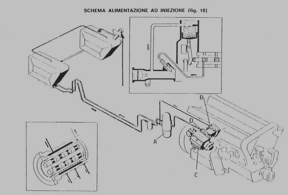
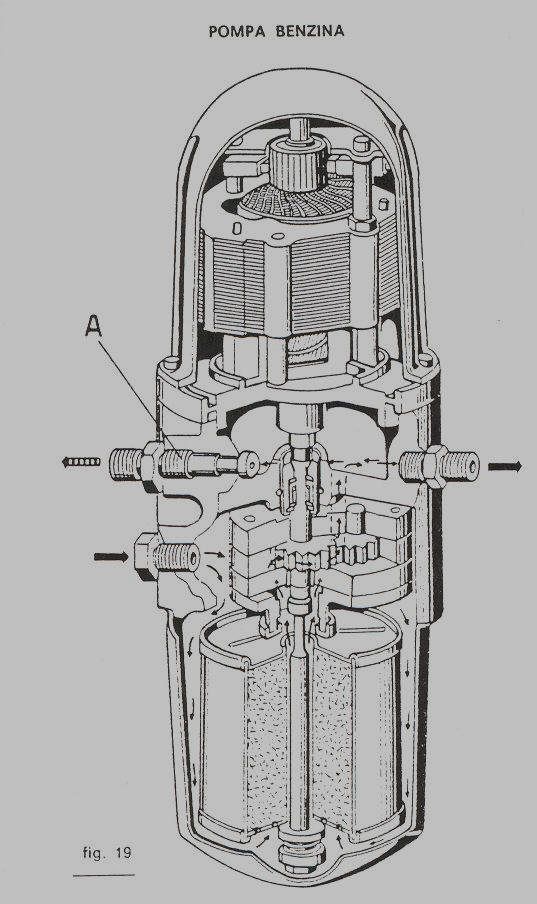
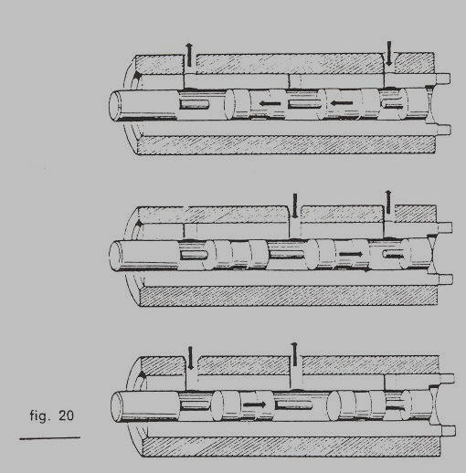
Figure 20 reproduces the outline of the distributor functions. It
is possible to see how
the movement of a rotor with specific apertures can connect the openings of the
small cylinders with pressurized gasoline, and how
the rotor itself, in a subsequent rotation, can put the same amount of gasoline
under pressure in connection with the tubing, which
leads from the metering unit to the injector. Also the control system shown in
figure 21, is as simple as its adjustment. This system defines
the quantity of fuel to be sent to the manifold in relation to the quantity of
air taken in by the cylinder. Its adjustment is done
through rollers or through springs, whose flexibility is very important. The
control scheme shown emphasizes in the points A,B,C,
the rollers, which coupled, determine the variation in the movement of the small
pistons of distribution. In points D and E,
we are showing the springs which control the location of the action of the small
rollers. The control device also has a device to
change the amount of fuel sent according to the barometric depression - point F.
Page 11
Click here to go to page 12