TRIUMPH 2.5 P.I. LUCAS MK2 SYSTEM
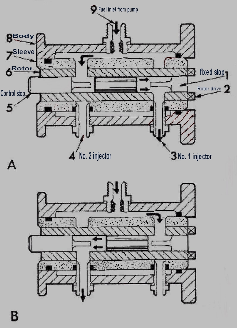
(Fig. 3A)Operation
This is a simple 2 cylinder example.
When the engine is started and the rotor turns within the sleeve, the rotor port at the control stop end becomes coincident with the port in the sleeve leading to the fuel reservoir in the body casting. Fuel at high pressure enters the rotor bore and drives the shuttle to the right (i.e., towards the fixed stop end of the rotor). This movement of the shuttle displaces fuel in the rotor bore through the ports in the rotor and sleeve to the injector serving No. 1 cylinder.
A further 180 degree rotation of the rotor
(Fig. 3B) causes the rotor ports at the fixed stop end to align with the sleeve
port leading to the fuel reservoir. Fuel now enters at the fixed stop end of the
rotor and drives the shuttle back towards the control stop end. An identical
quantity of fuel is displaced, by the shuttle as it moves to the left, by way of
the outlets in the rotor and sleeve to No. 2 injector.
In this way the shuttle continually moves between the two stops displacing an
accurate amount of fuel to each cylinder in turn.
The quantity of fuel delivered at each injection is dependent
upon the distance the shuttle travels, this distance is adjusted by the control
stop. On a road race car, the control stop is moved via a "fuel cam"
with linkage connected directly to the throttle shaft. On production
cars, the "control unit" dictates the position of the control stop
via intake manifold vacuum. The Lucas "road race" metering units
with a simple throttle controlled fuel cam are the least complex sequentially
timed mechanical fuel injection systems built.
Page 3
Click here to go to page 4
Click here to go to table of contents