TRIUMPH 2.5 P.I. LUCAS MK2 SYSTEM
Control Unit
Description
The control unit is attached to the metering unit by four nuts. A follower (15), with a diaphragm seal set in an annular groove around its periphery, projects through the leading face of the unit. The rear end of the follower bears against the outer two of three rollers (13) carried on the control links (12), whilst the third roller, of smaller diameter, runs against the fuel cam (11).
The control links are pivoted at the top where they are attached to the center of a spring-controlled rubber diaphragm, the lower part of the control links are free.
Two springs (3) are positioned between the diaphragm and three concentric calibration screws (4). The top of the diaphragm and the calibration screws are in a chamber connected by a pipe to the manifold.
The fuel cam (11) is secured by two screws to a carrier (8) which is in contact with an external control screw (14). The carrier is pivoted at point X, the pivot being extended through the rear face of the metering unit. The excess fuel lever (5) is pivoted at the rear face of the unit and has a cam face at the lower end which contacts the cam carrier pivot.
Operation
Engine fuel demands, according to throttle openings and load, are reflected in changes in inlet manifold depression. The change is sensed by the spring-loaded diaphragm, which takes up a position balancing the loading of the springs (3) against the depression in the chamber.
The control links are thus raised or lowered along the cam track allowing the follower to move further in or out of the forward face of the unit and so regulate the metering unit control stop.
To prevent the full hydraulic force of the control stop from impinging on the control linkage, a balancing spring (2) is fitted on the follower which results in only light pressure between the follower and the rollers.
The control springs at the rear of the diaphragm are chosen to suit the engine requirements. They are adjusted, during calibration, by the manufacturer and the adjustment MUST NOT BE DISTURBED.
The fuel cam (11) is secured to the carrier by two screws (C Fig. 16) the holes in the cam are slotted to enable the correct fuel control slope to be set. An external adjusting screw, acting on the fuel cam carrier, determines full load setting. The above adjustments MUST NOT BE DISTURBED.
Movement of the excess fuel lever is transmitted to the fuel cam and carrier which are pivoted at point ‘X’. When the lever is turned, the fuel cam and carrier are moved against the tension of the return spring, allowing the rollers, follower and control stop to take up a position providing up to 300% extra fuel.
Injectors
The injectors are fitted into the inlet manifolds and upon their performance depends the correct atomization of the fuel. A poppet valve in the injector is set to open at approximately 50 p.s.i. and give a 60 degree hollow cone spray.
SERVICE PRECAUTIONS
In addition to normal service precautions, the following are peculiar to petrol injection engines.
(a) Before subjecting a vehicle to a lengthy overhaul or a prolonged period of idleness, a petrol inhibitor should be added to the fuel and the engine run to ensure complete circulation throughout the system. The gummy residue, from evaporated petrol, is thus prevented from seizing the shuttle and other close- tolerance parts in the system.
(b) The fuel pump must not be switched on whilst any part of the pressurized circuit is disturbed.
(c) The fuel pump must not remain switched on for lengthy periods whilst the engine is stationary. If the ignition circuit is required to be switched on without running the engine for lengthy periods, disconnect the electrical connections to the pump.
(d) Do not re-use sealing rings, always use new ones.
(e) Subsequent to an overhaul it will take some time to re-prime the fuel system, therefore, crank with full choke until the engine starts. Do not attempt to re-prime with a battery in a low state of charge.
Piping and Unions
Because of the comparative high pressures used on the fuel system it is imperative that all union connections are securely tightened and that the piping is regularly inspected for fretting, kinking and leaks.
The rubber tubing used on the leak-off return pipe must be carefully replaced to prevent kinking and ensure that the steel pipe does not bite into the rubber and so block the pipe.
The leak-off pipe will, if blocked, cause a pressure build up in the metering unit which will prevent full recuperation of the follower and consequently allow excess fuel to be delivered, resulting in sooting up of the plugs combined with uneven running.
MAINTENANCE
Routine maintenance on the petrol injection system is restricted to renewing the fuel filter every 12,000 miles as follows:Lift the luggage compartment lid; turn back the carpet and remove the left-hand section of the floor panel.
Slacken the nut securing the filter clip to the reservoir stud. To prevent fuel leakage clamp the hoses on each side of the filter. Remove the hoses from the filter.
Fit the new filter with the side marked ‘IN’ connected to the reservoir hose. Release the hose clamps, tighten securing clip.
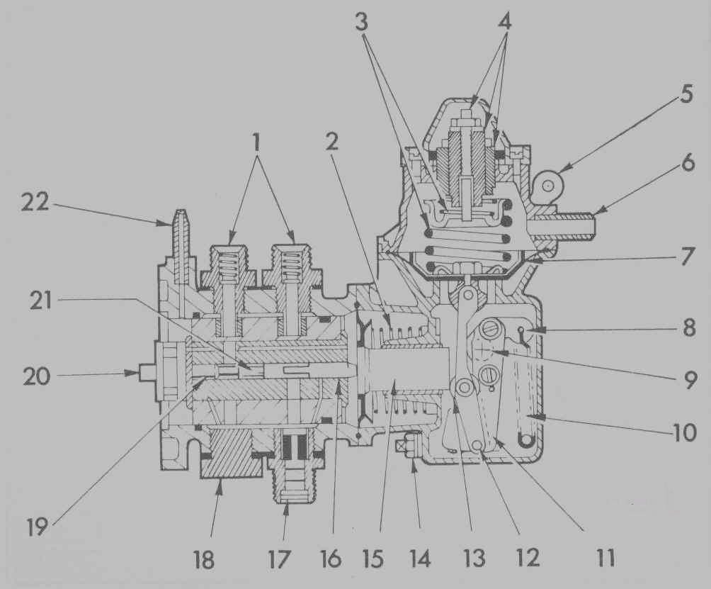
1. Outlet valves 12. Control
2. Balance spring 13. Rollers
3. Calibration springs 14. Full load setting screw
4. Calibration screws 15. Follower
5. Excess fuel lever 16. Control stop
6. Connection to manifold 17. Fuel inlet
7. Diaphragm 18. Blanking plug
8. Fuel cam carrier 19. Fixed stop
9. Pivot "X" 20. Rotor drive
10. Return spring 21. Shuttle
11. Fuel cam 22. Leakage fuel
Page 4
Click here to go to 5
Click here to go to contents