TRIUMPH 2.5 P.I. LUCAS MK2 SYSTEM
DESCRIPTION OF COMPONENTS
Fuel Filter (Fig. 2)
The fuel filter, situated below the luggage compartment, is an in-line full flow
type contained in a nylon case. The element and case are integral and require no
servicing but must be replaced every 12,000 miles.
Fuel Pump (Fig. 2)
The fuel pump, located below the luggage compartment floor consists of a
composite permanent magnet field motor driving a gear pump. Full
details of the pump and motor are contained in Group 6.
Pressure Relief Valve
The pressure relief valve is mounted with the pump and
filter below the luggage compartment floor. The
assembly comprises a simple adjustable spring- loaded relief valve screwed into
a brass ‘T’ piece, a nylon gauze strainer is incorporated into the assembly.
Reservoir
The fuel reservoir is of pressed metal construction
and is simply an extension of the fuel tank. No servicing
of the reservoir is necessary.
Metering Distributor Assembly
The metering distributor is mounted adjacent to, and
driven by, the ignition distributor driving gear. For ease
of description the assembly is dealt with in two parts, namely, the control unit
and the metering unit.
Metering Unit
Description
A gear drive from the ignition distributor
pedestal turns a rotor which has two radial ports to a central bore containing a
shuttle which is able to move axially between a fixed and an adjustable stop.
The rotor is contained within a sleeve with six outlet and six inlet ports
arranged in spaced pairs 60 degrees apart,
inlet and outlet alternating. The sleeve is sealed in a cast body having an
internal recess which forms a reservoir for pressurised fuel. Sealed outlet
valves connect the sleeve to external body connections for the injector pipes
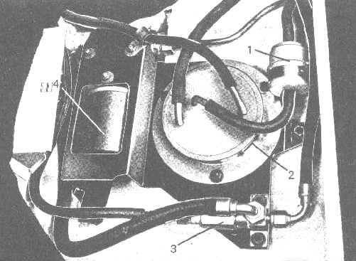
Fig. 2 Luggage compartment fuel system layout
1. Fuel filter
2. Fuel
reservoir
3. Pressure relief valve
4. pump
Page 2
Click here to go to page 3
Click here to go to contents