TRIUMPH 2.5 P.I. LUCAS MK2 SYSTEM
TRIUMPH 2.5 P.1. LUCAS MK. II SYSTEM
PETROL INJECTION
On the 2.5 P.I. a Lucas Mk. II petrol injection system replaces carburettors. This system delivers a fine spray of precisely timed and measured fuel to the air intakes via injectors. The mixture is then compressed and spark ignited in the usual manner.
The principles of operation as well as the relevant maintenance, overhaul, adjustments and fault finding procedures that can be associated with petrol injection are hereunder described.
It is envisaged that faults such as excess fuel consumption, poor performance, erratic running, etc., will be attributed to the fuel injection system, whereas they are more likely to emanate from other systems of the vehicle. It is, therefore, important to establish the correct functioning of the ignition, electrical, cooling and other systems and that sufficient clean fuel is available.
DESCRIPTION OF P.I. CIRCUIT
Using the schematic illustration (Fig.1) for reference, a brief description of the system is as follows:
Fuel from the tank (2) is gravity fed to a reservoir (4) from which it is drawn, via an in-line filter to an electrically driven pump (5). Pressurized fuel from the pump is passed to the metering unit (1) which meters and delivers fuel to each injector (9) in sequence.
Fuel line pressure from the pump is maintained at 106 to 110 p.s.i. by a pressure relief valve (6) which returns excess fuel to the tank.
The metering unit is driven in conjunction with the ignition distributor. Fuel is used to lubricate the metering unit and is then fed back to the tank.
The fuel reservoir acts as an anti-surge device, preventing loss of fuel to the pump on sharp turns, steep hills and sudden stops. A pipe, vented to the fuel tank, prevents air locks in the system.
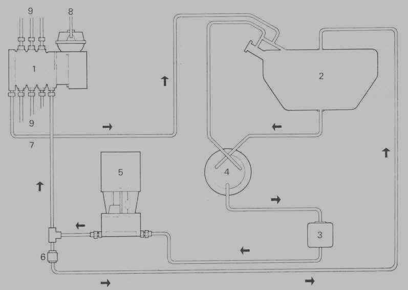
Fig. 1. Schematic view of P.I. circuit
1. Metering distributor and control
unit
6. Pressure relief
valve
2. Fuel
tank
7. Lubricating fuel return pipe
3. Fuel
filter
8. Vacuum connection to manifold
4. Anti-surge
reservoir
9. Injector pipes
5. Electrically driven fuel
pump
10. Fuel flow direction = arrows
Page 1
Click here to go to page 2
Click here for table of contents