Lucas Service Training Centre
Petrol Injection Mk II
10. DISMANTLING AND SERVICING OF FUEL PUMP AND MOTOR
The fuel pump and “permanent magnet” motor (Fig. 26) can be dismantled and re-assembled without the use of special tools.
A 110 volt A.C. mains connection will be required for insulation tests on the pump motor armature; and a lathe for skimming the armature should this be necessary.
Note: It is essential that the working area on the bench is clean (free of dirt, metal and swarf etc.) otherwise it will be attracted inside the yoke by the exposed field magnets. A piece of clean rag pushed into the yoke will help to keep out any dirt etc.
When re-assembling the yoke to the armature do not allow it to snap hard against the ceramic magnets and damage them.
(a) Dismantling Procedure
(i) Remove the six bolts which secure the pump unit to the pump housing and withdraw pump unit. (The pump unit components are not serviced individually. Fit a complete new unit if original is faulty).
(ii) Remove and discard the ‘0’ ring situated in the end of the pump housing.
(iii) Remove the two through bolts which secure the yoke to the housing. Grip the exposed tongue of the armature shaft with a pair of pliers and gently remove the armature and housing assembly from the yoke.
(iv) Hold the housing in a vertical position (armature uppermost) and gently withdraw armature from housing.
Note: At this stage the assembly must be held in a vertical position to ensure that the shimming washer(s) on the armature shaft slide off as the armature is withdrawn. Otherwise, they will stick to the armature and damage the brushes as the armature is withdrawn.
(b) Serviceability of Parts
(i) Brushes
Fit new brush plate assembly if brushes are worn to less than 0.125” (3.17 mm) in length.(ii) Armature
Use an armature tester to check armature for open or short-circuited windings. Check armature insulation using a 15W 110 volt A.C. mains test lamp connected between each commutator bar and armature shaft. Armature resistance between adjacent commutator bars should be within the limits 0.16 to 0.24 ohms at 150C.(iii) Commutator
The commutator should be cleaned using a petrol moistened cloth, and light scratches removed by polishing with a very fine glass paper. A badly scratched or worn commutator should be skimmed on a high-speed lathe. Do not remove more metal than is necessary. DO NOT UNDERCUT THE INSULATORS BETWEEN THE ARMATURE SEGMENTS(iv) Pump Unit
Visually examine for signs of wear etc. The pump unit must be renewed, if worn, as component parts are not serviced individually.(v) Coupling
Visually examine for signs of wear etc., and renew if necessary.(c) Pump Motor Rubber Seal
Evidence of petrol discharge from the small drain pipe on the body casting indicates failure of the rubber seal
(between the pump and motor) through which the drive shaft passes. In such cases fit a new seal. To check the seal proceed as follows:(i) Connect the pump inlet to a kerosene supply.
(ii) Connect a pipe to the pump outlet union, and immerse the free end in kerosene.
(iii) Connect the motor cables to a 12 volt D.C. supply.(iv) When the pump is running and held well above the kerosene supply a continuous flow of bubbles discharged from the outlet pipe indicates that the seal is faulty.
(d) Re-assembly of Pump and Motor
Re-assembly of the pump and motor is the reverse of the assembly procedure. Great care must be taken to avoid damaging the thicker petrol seal (see 12 in figure 26) when passing the armature
shaft drive tongue through the base casting. The seal should be smeared with grease (Shell 6266) before assembling and a temporary protective cover fitted over the end of the armature shaft. (Figure 27 gives the dimensions for making a suitable cover. Alternatively, the bullet-shaped cap from a ball-point pen can be used as a protective cover).Ensure the assembly marks (see 13 in Figure 26) on the motor yoke and body casting are in line when assembling them together, otherwise reverse rotation will result.
Bolt pump and motor together after checking that the drive assembly is satisfactory, and correctly located.
(e) Armature End-Float Adjustment
After assembling pump and motor, hold the pump unit with the yoke vertical (end-float adjustment screw uppermost) and proceed as follows:
(I) Slacken the locknut for end-float adjustment screw and screw in adjuster until resistance is just felt. Screw the adjuster back a 1/4 of a turn to give the correct end-float within the limits 0.004” to 0.010” (0.10 mm to 0.25 mm). Lock the screw in position.
(f) Light Running Test
Nom. voltage: 12 volt.
Light running current: at 13.5 volt and 2200
rev/min is 1.4 amperes.
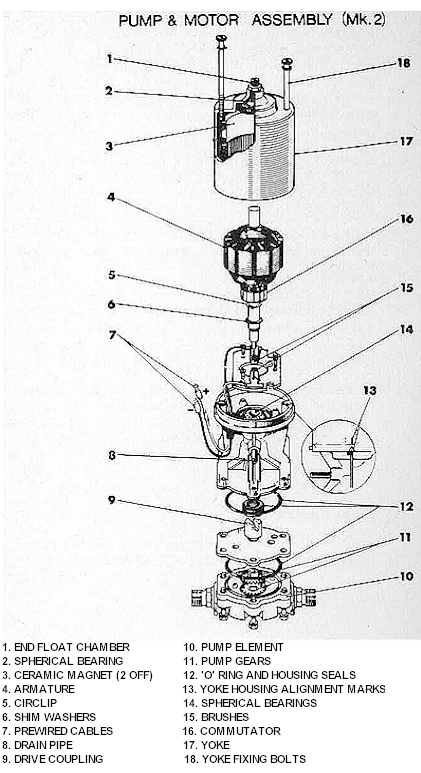
Fig. 26
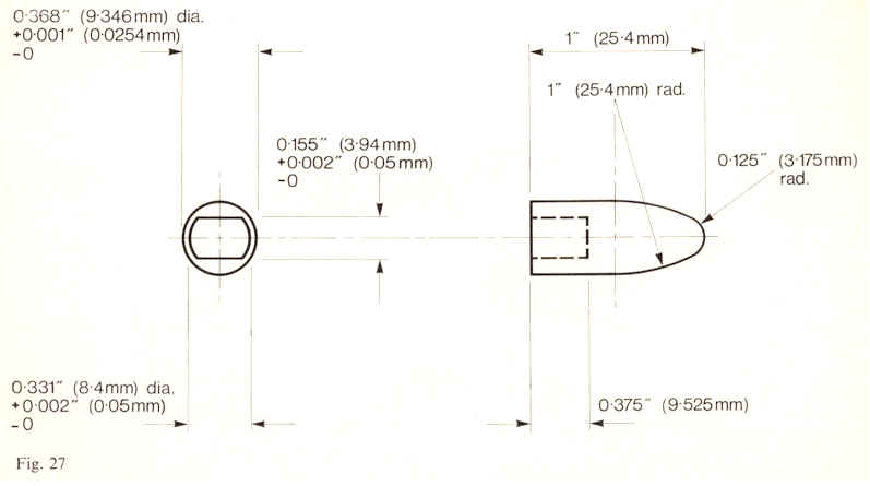
Fig. 27
Page 27 and 28
Click here to go to page 29