Lucas Service Training Centre
Petrol Injection Mk II
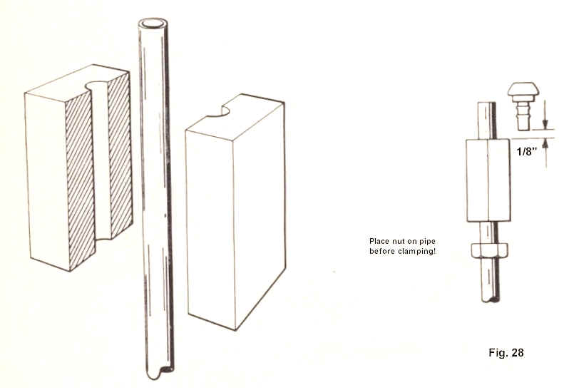
11. FITTING UNIONS ON FUEL INJECTION PIPES
In order to fit unions to fuel pipes, a suitable pipe clamp must be provided.
Figure 28 illustrates a simple clamp made from Tufnol block (approximately 2” x 1” x 1”). A 1/4"diameter hole is drilled through the centre of the block, which is then cut along its centre line. Cut the piping to the required length and clamp it as shown in Figure 28. Allow approximately 1/8" clearance above the clamp, in addition to the length of pipe required. If a straight connection is being made, place the union nut over the pipe before it is clamped.
Locate the connector in the pipe and gently tap it into its final position, using a soft-headed hammer. Remove dust particles from the interior of pipe with compressed air.
Note: The pipe must not be heated and the union assembly should be fitted cold. Part Numbers for ordering piping and respective connectors are as follows:
Piping (50 ft)...............................................................54733455
Elbow connector.........................................................54730924
Banjo..........................................................................54731886
Straight connector........................................................54733399
12. BENCH TESTING RELIEF VALVE
This test should be made with the relief valve connected to a suitable test rig. Test fuel must be Fawley White Spirit 100 inhibited with 50 p.p.m. (parts per million) Santolene ‘C’. (See Section 17, page 30).
The procedure is as follows:
(i) Assemble relief valve to test rig and flush the valve several times with test fuel from 0—25 g.p.h. to ensure the valve is clean before proceeding with tests.
(ii) Slowly increase pressure to 20—25 lbf/in2 (137.89—172.36 kN/m2). Check that air bleed is functioning. (There must be a minimum flow of 1 gallon per hour (g.p.h.) with the bleed open). Check that bleed closes at pressures above 25 lbf/in2 (172.36 kN/m2) indicated by bleed flow reduction.
(iii) Slowly increase pressure to 100 lbf/in2 (689.50 kN/m2). At this pressure maximum leakage flow rate should be 14- g.p.h.
(iv) Increase pressure until a flow rate of 17 g.p.h. is obtained and note pressure. This must not exceed 108 lbf/in2 (744.60 kN/m2).
(v) Reduce pressure to 100 lbf/in2 (689.50 kN/m2) and note leakage. This must not exceed 14-g.p.h.
(vi) Drain off excess fuel from valve.
13. BENCH TESTING PUMP AND MOTOR UNIT
Test fuels to be “Shell Super” 100 octane petrol, reference fluid SBP 62/68 or Fawley White Spirit 100 inhibited with 50 p.p.m. Santolene ‘C’. Proceed to test as follows:
(a) Functional Tests
(i) Connect a 13.5 volt supply to the motor and set the pump delivery pressure to 100 lbf/in2 (689.50 kN/m2). Pump delivery and motor current should be as follows:
Minimum Flow Maximum Current
(g.p.h.) (Amps)
16 (100 octane) 5.0
15 5.2
(ii) Connect an 8 volt supply to the motor and set pump delivery pressure to 100 lbf/in2 (689.50 kN/m2). Pump delivery and motor current should be as follows:
Minimum Flow Maximum Current
(g.p.h.) (Amps)
Zero flow (100 octane) 6.0
Zero flow 6.3
(iii) Check that pump will continue to run down to 6 volts at zero flow.
During the tests check unit for external leakage, particularly around joint faces of pump components and the seal leakage drain tube. See Figure 29 which shows test fuel comparison curves.
(b) Inhibiting
If tests have been carried out using inhibited Fawley White Spirit 700, no further inhibiting is necessary. If the test was made using petrol or SBP 62/68 fluid, it will be necessary to inhibit as follows. With a minimum head of 12 inches (304.8 mm) of clean filtered Shell Fusus ‘A’ or inhibited Fawley White Spirit 100, the pump must be run for one minute with the delivery pressure set at 100 lbf/in2 (689.50 kN/m2). Drain off any excess oil from unit.
Page 29
Click here to go to page 30
Click here to go to the table of contents