Lucas Service Training Centre
Petrol Injection Mk II
6. BENCH TESTING THE METERING DISTRIBUTOR/CONTROL UNIT
Having made the initial adjustments, the metering unit is tested to check the fuel output over the full operating range (including maximum and minimum requirements).
The output requirements of the metering unit vary with the vehicle to which it is fitted, so ensure that it is checked against the correct figures.Important
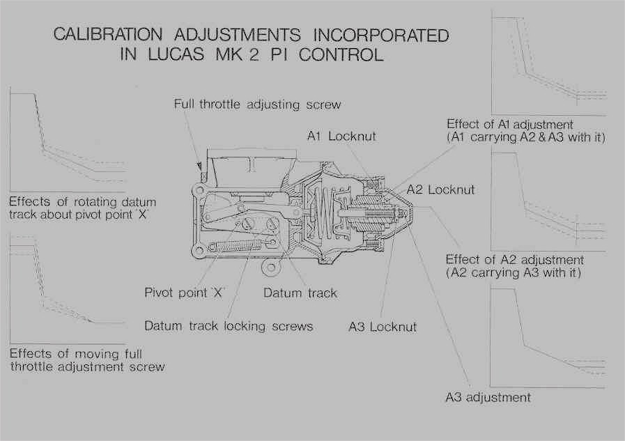
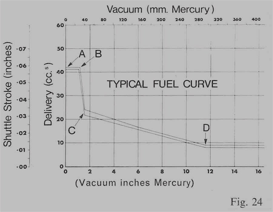
If the output performance does not conform to specification, the metering unit requires recalibrating. The adjustment of the calibration screws affects the fuel output and hence the performance of the vehicle (see Figures 24 and 25).(a) Testing Procedure
(i) Bolt the metering distributor to the drive flange of the test bench. Ensure that the unit is mounted in the same position as on the vehicle. (Control datum track should be vertical). Remove rectangular cover plate.
(ii) Connect outlet unions to injector pipes.
(iii) Connect measuring glass to leak off drain. Connect fuel supply to inlet connections.
Note: Test fuel should be Fawley White Spirit No. 100; plus 50 parts per million Santoline ‘C’ inhibitor, or Shell Calibrating Fuel ‘C’.
(iv) Switch on test bench and gradually increase speed to 1000 rev/mm. Operate overfuel lever several times over full movement. Check that there is approximately the same amount of fuel in each sight glass. Fuel should be dripping from the leakage drain.
This check proves that there are no obvious faults such as leaking or blocked pipes etc. It also ensures that all air is removed from the pipes.
(v) Connect a variable vacuum supply 0-28” Hg (711.2 mm) to the control unit depression chamber. Increase vacuum to approximately 25” Hg (635 mm) and then reduce to zero. Repeat this at least five times to eliminate any “sticking” in the depression chamber or on the datum track.
(vi) Check that there is a clearance of 0.004-0.008” (0.10-0.20 mm) between overfuel lever and adjustment screw which bears on the cam.
(vii) Maintain speed of test bench at 1000 rev/mm, and fuel supply pressure at 100 lbf/in2 (689.50 kN/m2).
Check performance of metering distributor/control unit.
Adjust vacuum to minimum figure in specification tables, and check the amount of fuel delivered to each sight glass.
Then, adjust vacuum to next figure in the table, and again check amount of fuel delivered.Fig. 25
Page 24
Click here to go to page 25