Lucas Service Training Centre
Petrol Injection Mk II
7. ALTERNATIVE TESTING PROCEDURE
If a fuel injection test bench is not available, there is an alternative method of checking the output performance of the metering unit.
This involves measuring between the cam follower face and the rollers on the datum track, at various vacuum gauge readings,
and checking the amount of roller travel.The equipment required is:
(I) a variable vacuum supply, 0—26” Hg (711.2 mm);
(ii) a set of flat feeler gauges;(iii) a pair of dividers, and
(iv) a datum track locking tool.
(a) Testing Procedure
Bolt the metering unit to a metal plate. Clamp the plate in a vice so that the unit is in the same plane as when fitted to the vehicle,
that is, with datum track vertical. The testing procedure is as follows:(i) Check clearance between overfuel lever adjustment screw and cam on which it runs.
Clearance should be within the limits of 0.004”—0.008” (0.l0—0.20 mm) when lever is in the “at rest" position.(ii) Remove large (datum track) rectangular cover, and insert locking tool.
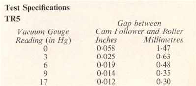
(iii) Check that gap between cam follower face and rollers is 0.058 (1.47 mm) in “at rest” position.
Reset if necessary, by adjusting the maximum fuel screw with locking tool removed. Re-insert
locking tool and again check clearance.(iv) Connect variable vacuum supply to the depression chamber.
(v) Increase vacuum to approximately 25” Hg and then reduce to zero. Repeat this at least five
times to eliminate any “sticking” in the depression chamber or on the datum track.(vi) Roller travel should be 0.540” (13.72 mm) check as follows:
(a) Measure distance of edge of rollers from a datum point on control box with a pair of dividers.
(vii) Increase opening of dividers by 0.540” (13.72 mm).
(viii) Apply a depression of at least 25” Hg to depression chamber.
(ix) Again measure distance from original datum point to edge of roller with reset dividers.
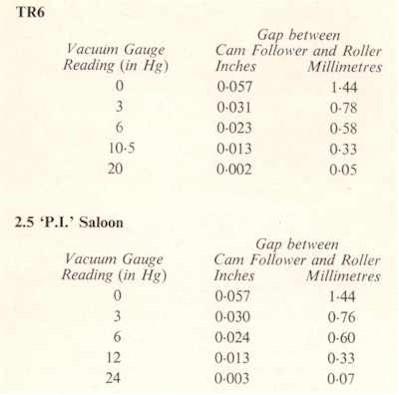
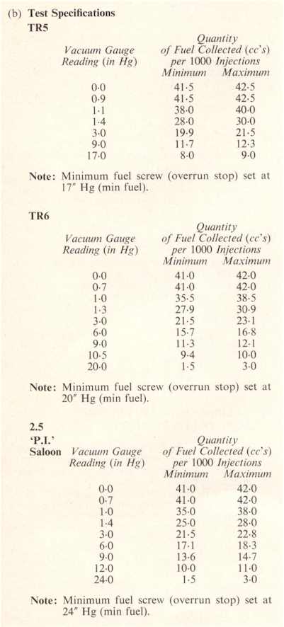
Rollers should have moved 0.540” (13.72 mm).(x) Check the gap between cam follower face and roller at different depressions as shown in the specification tables (b).
Note: The feeler gauge must be inserted in line with the centre of the rollers, and must be in contact with both roller edges.
The feeler gauge should slide easily between the rollers and the cam follower.
|
|
|
Page 25
Click here to go to page 26