Lucas Service Training Centre
Petrol Injection Mk II
(Continued)
(v) Fit a flat washer and secure the assembly with a circlip.
(vi) Fit the pivot shaft/datum track spring.
(vii) Assemble the rollers to the control links - small roller in the middle, large rollers
with chamfered edge facing inwards. This should be done by first fitting the roller
pivot to one of the links and securing with a circlip. The rollers can be located in position
by rotating the link so that the pivot pin is uppermost.(viii) Next, place the spherical bearing in position at the end of the link.
(ix) Fit the remaining link arm and secure with circlip.
(x) Replace the backing plate, diaphragm, diaphragm support and spring seat in that order.
(xi) Screw on the diaphragm locking nut and tighten to 4 lbf (17.80 N).
(xii) Lightly smear link rollers with a little Rocol MD-0.
(xiii) Re-fit link arm and diaphragm making sure that spherical seat and link arm are
square with the rest of the assembly.(xiv) Push diaphragm rim into its seating on the body.
(xv) Assemble calibration springs - large spring on the diaphragm, then spring carrier
and small spring.(xvi) Fit depression chamber cover and overfuel lever bracket. The bracket should be
positioned so that its cranked end is nearest the drive end of the metering distributor.
The air inlet connection must be positioned on the opposite side to the banjo connections.
Note that the two longest fixing screws are used on the bracket side of the cover.(xvii) Position the cam follower diaphragm with the three locating slots uppermost, feed
cam follower through hole in diaphragm. (The diaphragm can be pushed on to its seating
on the cam follower by finger pressure).
4. RE-ASSEMBLY OF METERING DISTRIBUTOR TO CONTROL UNIT
(i) Fit spring thrust plate over cam follower.
(ii) Position cam follower and spring between the control unit and metering distributor and
secure one to the other. Ensure that the diaphragm seal is seated correctly.
5. SETTING THE DATUM TRACK ANGLE
After re-assembling the metering unit, some mechanical settings or adjustments must be made
before the unit is tested on the test bench.Note: These initial adjustments ensure that the angle of the datum track is correct.
Otherwise, there will be reduced performance at engine idling speed and at light load
conditions. When setting the metering unit, adjust the maximum fuel screw and the
datum track to obtain the required gap between rollers and cam follower.The complete calibration procedure is necessary if the calibrating screws have been moved
from their original setting.(a) Test Equipment Required
(i) A fully equipped fuel injection test bench.
(ii) A set of flat feeler gauges.
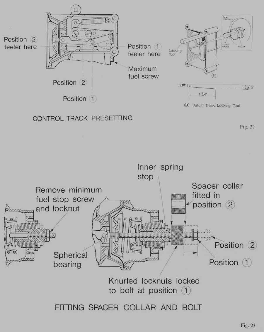
(iii) A tool to assist in the setting operation. (A 16AC end bracket fixing bolt can be
used, provided it is threaded along its entire length. Alternatively, a 5/16“ UNF bolt,
at least 3k” (89 mm) long, with two locknuts can be used, see Fig. 23.(iv) A collar 0.540” (13.72 mm) thick to fit over the bolt. See Fig. 23.
(v) A datum track locking tool (see Fig. 22a).
(b) Setting Procedure
The procedure concerns adjusting the control unit datum track to the correct angle,
and also the amount of roller travel. With the metering unit bolted to the test bench
the sequence is as follows:(i) Remove plastic covers from the depression chamber and datum track housing.
Note: Replace the depression chamber cover fixing screws.
(ii) Remove minimum fuel stop screw and locknut, see Fig. 23.
(iii) Insert locking tool and check that clearance between the roller and the cam follower
(see Fig. 22, position 1), is 0.058” (1.47 mm).(iv) If incorrect, remove locking tool and adjust datum track by means of the maximum
fuel screw until 0.058” (1.47 mm) clearance is obtained. Repeat (iii) with locking tool in
position.(v) Insert 5/16“ UNF bolt complete with locknuts in place of minimum fuel stop screw.
Screw bolt until it just bottoms on the spherical bearing stop pin, see Fig. 23.(vi) Screw locknuts against inner spring stop and lock together on the bolt.
(vii) Unscrew bolt with both nuts locked together, until 0.540” (13.72 mm) collar
just fits between locked nuts and inner spring stop, see Fig. 23.(viii) Apply vacuum to depression chamber. (17” Hg for TR5 unit and 24” Hg for TR6
and 2.5 ‘P.I.’ units).
(ix) Place a flat feeler gauge between roller and cam follower. 0.012” (0.30 mm) for
TR5 unit and 0.002” (0.050 mm) for TR6 and 2.5 ‘P.I.’ units.) See Fig. 22, position 2.
(x) Loosen the two datum track securing screws and adjust datum track until required
clearance is obtained. Re-tighten securing screws and check clearance.
(xi) Return depression chamber to atmospheric pressure and re-check 0.058”
clearance at position 1 (see Fig. 22) re-adjusting if necessary. Re-fit the minimum fuel stop
screw and locknut.
Page 22 and 23
Click here to go to page 24
Click here to go to the table of contents