Maserati Manual MK1
Mistral + 3500 GT Owner's Manual
THE METERING DISTRIBUTOR AND MIXTURE CONTROL UNIT
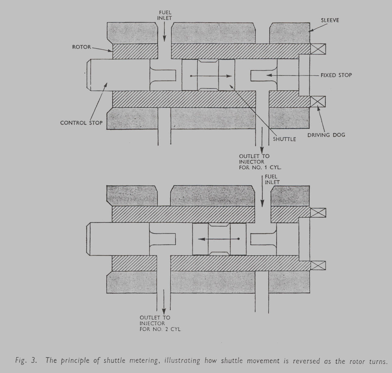
The Principle of Shuttle Metering
The principle of shuttle metering is illustrated in Fig. 3 which shows an
arrangement suitable for a two-cylinder
engine. An engine-driven rotor, having two radial ports leading to a bore in its
centre, fits in a sleeve containing fuel
inlet and outlet ports. The bore of the rotor contains a small shuttle capable
of moving axially between two stops. one
fixed and the other adjustable. As the rotor turns within the sleeve, the rotor
port at the control stop end becomes
coincident with the fuel inlet port in the sleeve (as shown in the upper
diagram). Fuel from the pump now enters at
pressure and drives the shuttle towards the fixed stop. displacing fuel which is
discharged through the rotor and sleeve
ports at that end to an injector. A further 180 degrees of rotation of the rotor will
result in the position shown in the lower
diagram, fuel now enters at the fixed stop end of the rotor. driving the shuttle
towards the control stop and displacing
an identical quantity of fuel to the second cylinder. In this way. the shuttle
moves to and fro between the two stops as
the rotor is driven round, and at each shuttle movement an accurately metered
amount of fuel is displaced and injected
into the appropriate cylinder. The quantity of fuel is the product of the area
of the bore and the distance of shuttle
travel. the latter being determined by the setting of the control stop.
Page 6
Click here to go to page 7
Click here to go to the table of contents