Maserati Manual MK1
Mistral + 3500 GT Owner's Manual
Petrol Injection Equipment
INTRODUCTION
On a petrol injection engine, the carburetor is replaced by a pressurized fuel
system which meters accurate charges
of fuel to each cylinder in turn. The fuel is injected in the form of a fine
spray into the intake air at a point in the
manifold close to the inlet valve. The mixture is then compressed and
spark-ignited in the usual manner.
The accurate control possible over the amount of fuel supplied to each cylinder
under all operating conditions
gives increased economy and greater flexibility to a petrol injection engine. In
addition the removal of the carburetor
choke, and the absence of the exhaust-heated hot spot, permit an increased air
charge to the engine, resulting in increased
power output.
As a result of many years of investigation into problems associated with petrol
injection, Lucas engineers have
developed a system which will serve four, six or eight cylinder engines
accurately and reliably. The ability of the system
to meet very high speed requirements is shown by its successful use on specially
designed racing engines with speeds
of the order of 10,000 r.p.m.
GENERAL DESCRIPTION OF THE SYSTEM
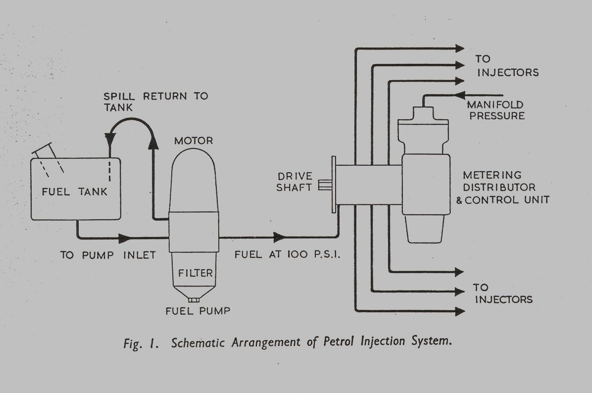
The system is illustrated schematically in Fig. 1. Briefly. a motor-driven
primary pump. mounted on the chassis
adjacent to the fuel tank, supplies fuel at a pressure of 100 p.s.i. to the
metering distributor mounted on, and driven by,
the engine. From the metering distributor, accurately timed and metered,
quantities of fuel are delivered at each
injector in turn; these are of poppet valve type, located in the manifold near
the intake ports, the fuel being discharged
into the intake air stream in the form of finely divided spray.
When the system is fitted to normal production high-performance engines, the
amount of fuel metered to the individual
injectors is determined automatically by the mixture control unit described on a
later page. This unit is mounted
integral with the metering distributor and takes its signal from a tapping on
the intake manifold. For racing engines,
which normally have a limited operating range at the upper end of the r.p.m.
scale, fuel control is achieved directly
by means of a profiled lever mounted on the metering unit and actuated by the
throttle linkage.
THE FUEL PUMP
The fuel pump (see Fig. 2) comprises a simple gear pump driven by a permanent
magnet motor operating at battery
voltage, and incorporates a paper filter element in the main fuel supply. A
relief valve returns excess fuel to the tank
and maintains the line pressure at 100 p.s.i.
Page 4
Click here to go to page 5