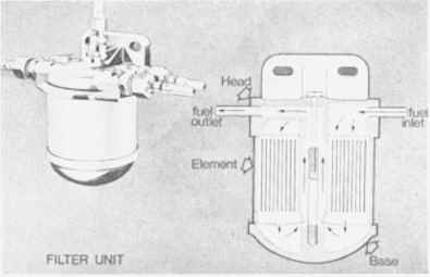
LUCAS INJECTION

Lucas MK1 and MK2 fuel / petrol injection


HOME     HISTORY     TECH     LINKS     REBUILDING     MANUALS     FAQ     PROJECTS    YOUR CAR  
FUEL CAMS
     PLUMBING     PICTURES     STREET     LINKAGE + DRIVES      ENGINES       


Lucas Service Training Centre
Petrol Injection Mk II


Part 1


General Description of Petrol Injection System


                           Fig. 2


Figure 2 shows the main components in the Lucas Mark II petrol injection system. Fuel from a gravity- feed tank maintains the level of fuel in the filter. The pump together with the pressure relief valve draws fuel from the filter and maintains the fuel pressure in the supply line at 100-110 lbf/in2 (689.50-758.50 kN/m2). (Depending on installation, the valve returns excess fuel either to the filter or the petrol tank.)

Pressurised fuel is supplied to the metering distributor, which is driven from a suitable engine take-off point. Fuel charges are delivered to each cylinder in turn, by means of the injectors. The amount of fuel in these charges is varied to suit the engine requirements by means of the mixture control unit, which forms a composite unit with the metering distributor.


Components of the Petrol Injection System


                                                                  Fig. 3
FILTER UNIT

Fine particles of abrasive matter and water are often carried in suspension in the fuel. If these were allowed to pass into the system, they would cause excessive wear or corrode the precision-finished surfaces of the metering distributor and pump etc., resulting in poor engine performance and loss of power. The petrol must be filtered before entering into the system.

This is done by passing it through a special filter unit, the filter of which consists of paper strips, wound about a cylindrical core. These paper strips are cemented together, top and bottom, so as to form a series of V-shaped coils. The element provides a large filter area (approx. 550 sq.in).

Filter Units (Sectioned) Diagrams

Figure 3 shows the three main components of the
simple filter unit.

1. The filter head, made of cast aluminum. The head incorporates all fuel connections (inlet and outlet).

2. The base, made of cast aluminum, with centre stud (to accept the centre bolt of the filter head).

3. The sedimenter element, enclosed in a metal container.  The three components of the filter are held together by means of the centre bolt, which screws into the centre stud, one end of which is screwed in the base.


Page 7
Click here for page 8

Click here to go to the table of contents