Lucas Service Training Centre
Petrol Injection Mk II

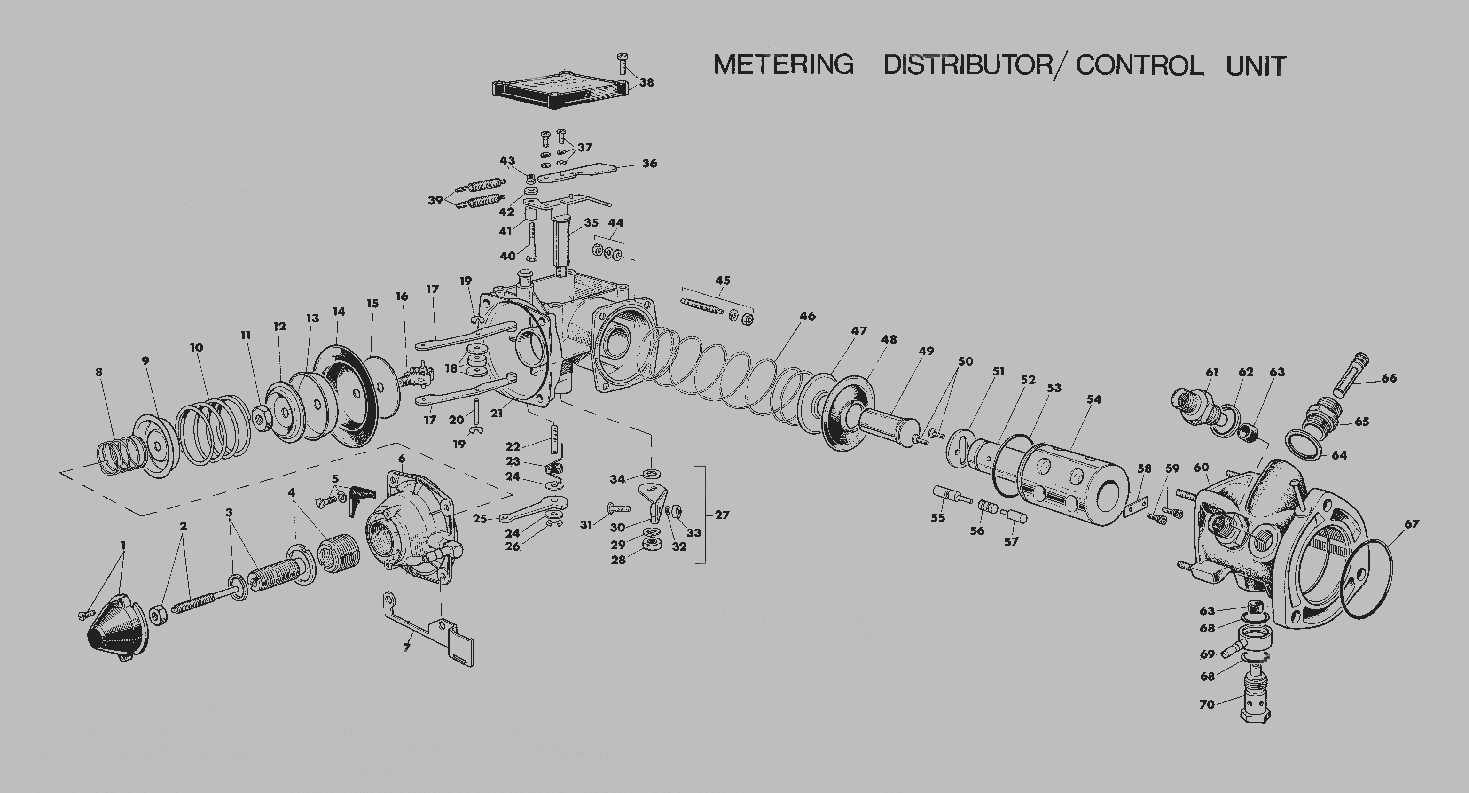
Fig. 18
KEY TO (FIGURE 18) EXPLODED ILLUSTRATION OF METERING/CONTROL UNIT
1. Depression chamber cover and fixing screws (2 off).
2. Centre (minimum fuel) screw and locking nut.
3. Intermediate calibration screw and locking ring.
4. Outer calibration screw and locking ring.
5. Depression chamber fixing screws and washers (4 off) and unit part number plate.
6. Depression chamber body.
7. Overfuel lever bracket stop.
8. Outer calibration spring.
9. Calibration spring carrier.
10. Inner calibration spring.
11. 1/4 UNF nut.
12. Thrust plate.
13. Diaphragm support.
14. Diaphragm.
15. Diaphragm support plate.
16. Spherical bearing and datum link arms pivot.
17. Datum link arms.
18. Datum rollers - 2 outer I inner.
19. Datum link arm circlips.
20. Roller and link arm circlips.
21. Body assembly.
22. Overfuel lever pivot.
23. Overfuel lever return spring.
24. Washer.
25. Overfuel lever.
26. Circlip.
27. Overfuel lever assembly (with adjustment cam follower) screw.
28. 1/4 UNF nut.
29. Spring washer.
30. Overfuel lever.
31. Cam follower adjustment screw.
32. Spring washer.
33. No. 6 UNC nut.
34. Spacer.
35. Datum track pivot arm assembly.
36. Datum track.
37. Fixing screws, No. 6 UNC nut and plain washer.
38. Datum track assembly cover and fixing screws No. 10 UNF (9 off).
39. Datum track spring(s).
40. Spring(s) anchor pin.
41. Spring spacer.
42. Spacer.
43. Locktite nut.
44. Nut, spring washer and plain washer (4 off each) distributor body fixing.
45. Maximum fuel screw spring washer and No. 10 UNF nut.
46. Cam follower spring.
47. Thrust plate.
48. Diaphragm seal.
49. Cam follower.
50. Rotor thrust plate (socket-headed countersunk) fixing screws.
51. Rotor thrust plate.
52. Rotor.
53. Sleeve ‘0’ ring.
54. Sleeve.
55. Control stop.
56. Shuttle.
57. Fixed stop.
58. Rotor retaining plate.
59. Fixing screws (socket-headed).
60. Body assembly.
61. Outlet union.
62. Sealing washer.
63. Seal.
64. Sealing washer.
65. Inlet union.
66. Filter.
67. Metering distributor body ‘0’ ring.
68. Banjo ‘0’ ring seal.
69. Banjo connector.
70. Banjo bolt.
Page 18 and 19
Click here to go to page 20