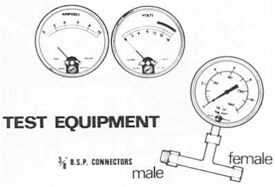
TEST EQUIPMENT
The following items of test equipment are required for
checking the petrol injection system:
(i) Pressure gauge (see Figure 13) scaled for
reading up to at least 160 lbf/in2 (1103.20 kN/m2).
(ii) A ‘T’ piece, two -3/8” B.S.P.
connections (one male and one female) and a suitable connection for the
pressure gauge.
(iii) A vacuum gauge 0-26” Hg (0-711 mm Hg).
(vi) Ammeter (scale 0-10A).
(v) Voltmeter (scale 0-18V).
Important:
The fuel pump should never be switched
on while any part of the fuel system, normally pressurized, is
dismantled. Further, the fuel pump should not be run for long periods,
when the engine is stationary. The following precautions should also be
taken before carrying out systematic fault diagnosis:
(I) Whenever the pipes are removed from the petrol injection system, and
the ignition is switched on, the feed cables must be disconnected from
the pump.
(ii) Cover exposed pipe with blanking plugs.
(iii) Any sealing ring, removed during testing must not be re-fitted,
but must be renewed.
When checking the ‘PI’ system the test equipment should be
connected as follows:
(a )Vacuum gauge: ‘T’ piece between (center pair) air intake
manifold and the metering distributor vacuum connection.
(b) Pressure gauge: ‘T’ piece connected into petrol inlet at
metering unit.
(c) Voltmeter: Connected across pump motor terminals.
(d) Ammeter: Connected in series with either of the pump motor leads.
With engine running at ‘tick over’ speed (850 rev/ mm) gauges and
meters should read as follows:
Pressure gauge: 100-110 lbf/in2 (689.50-758.50 kN/m2) all
models.
Vacuum gauge: TR5/6 7” Hg (180 mm Hg) 2.5 litre 12” Hg
(305 mm Hg).
Volt drop should not exceed 1.5 volts. Ammeter: should
read not more than 5.5 amps.